Activity 8 : 3D Surface Reconstruction from Structured Light
In this activity, we try to reconstruct volume objects by projecting different patterns to the volume object rather than taking a stereoscopic image of the object (only 1 surface view of the object is utilizes instead of 2). This is specially useful in the field of archaeology, marine biology and other fields where non-destructive reconstruction and measuring techniques for artifacts are needed.
The following image shows the setup for this technique.

Setup: (a) projector, (b) camera [1]
Here, instead of two cameras, the method utilizes a camera and a projector. The distance between the camera and the projector is known, as well as the distance between the camera and the object being measure. In addition, the focal points of the camera has already been pre-measured.
The patterns to be projected to a volume object is a set binary gray code images. The images projected to the object volume is shown below.

Binary images projected to the volume object
These binary code images, which can also be treated as logical matrices, will then be multiplied with increasing powers of two. After each pattern is multiplied by a power of two, the resulting matrix will be added to other resulting matrices to come up with a matrices with its column values unique. This process is illustrated below.

Binary images to graycode matrix [1]
For this activity, the volume object used is a rectangular pyramid. The resulting images are shown below.

Patterns projected to the volume image
The resulting binary code images, for both reference plane and object planes, are shown below.
For the reference plane, noise and inaccuracies in the grayscale to BW conversion resulted to noisy (or warping) columns. To fix this, the first row was assumed to be accurate and used as a base for other rows. The result was a matrix with more distinct columns.
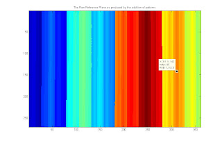
Reference plane as produced by adding the gray coded binary images
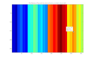
The reference plane fixed by setting all the rows equal to the first row
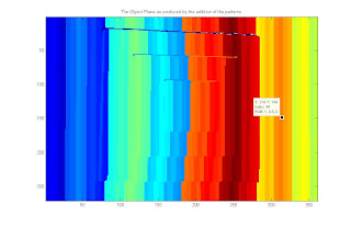
The object plane produces by adding the gray coded binary images
projected to the volume object
The reconstruction of the volume object roots from the fact that when a volume object was projected with the binary patterns, the patterns will be distorted proportional to the contours and height of the object. It can be verified by looking into the object plane image above and comparing it to the reference plane. The shape of the object volume can be visually reconstructed based from the distortions of the different columns. This is the theory behind 3d reconstruction from binary images.
Shown below is the illustration on how the algorithm derives the height of an object based upon the distortion of a column.

Height derivation from column distortion [1]
Using the concept of similar triangles and the focal length which is unique for the camera used, the following equations show how to get the height.

Equations to solve for height 'z'
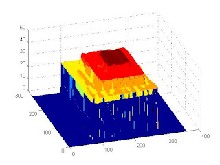
The images below show the resulting reconstruction. The first image is the raw reconstruction. Since the input images aren't perfect (note the shadows in the top portion of the pyramid), extreme values can be obtained resulting to erroneous height calculations. This was corrected by utilizing prior knowledge about the volume. Since we know that the middle part is the highest portion, we remove all heights that are higher than the middle portion of the pyramid. A 2-dimensional median filter is then utilized to even out the heights.
Raw object volume reconstruction
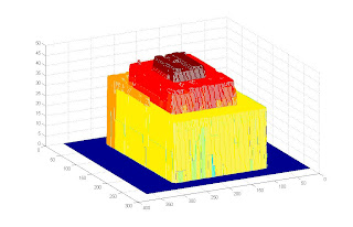
Reconstructed object volume further processed
We can see that the final reconstructions still has variation in height, especially in the first level. This can be traced due to the variation in the lighting present in the images where the patterns were projected to the volume. Below is one of the images.

Green box area: Area where light seem to flash out the black stripes
We can see that the portion highlighted by the box shows some of the black columns are not as black or emphasized as those in the upper portion of the volume. This would have an effect when the image is converted into a logical image as the columns of zeros and ones would not be as distinct. This is similar to the raw reference plane that we have seen above. Since the columnsa aren't as solid as planned, distortions would appear.
Still, the reconstructed volume is very similar to the object volume and we could conclude that the method works.
Code Listing:
function cropall
%
gthresh = 0.6;
width = 360;
height = 270;
refplaneraw = zeros(height+1, width+1);
objectplane = refplaneraw;
% rect = [470 310 width height];
levels = 7;
for i=1:1:levels
reffile = strcat('newrefimage_', num2str(i), '.jpg');
objfile = strcat('newimage_', num2str(i), '.jpg');
refimage = imread(reffile);
objimage = imread(objfile);
% newimage = imcrop(temp, rect);
gthreshobj = graythresh(objimage);
gthreshref = graythresh(refimage);
BWrefimage = im2bw(refimage, gthreshref);
BWobjimage = im2bw(objimage, gthreshobj);
objectplane = objectplane + double(BWobjimage*(2^(levels-i)));
refplaneraw = refplaneraw + double(BWrefimage*(2^(levels-i)));
end
refline = refplaneraw(1,:);
refplanefixed = refplaneraw;
for i=1:1:size(refplanefixed ,1)
refplanefixed (i,:) = refline;
end
close all
figure, imagesc(refplaneraw);
title('The Raw Reference Plane as produced by the addition of patterns');
figure, imagesc(refplanefixed);
title('The Reference Plane with the columns fixed to a constant column width');
figure, imagesc(objectplane);
title('The Object Plane as produced by the addition of the patterns');
save patterns.mat refplaneraw refplanefixed objectplane
%% %
load patterns.mat
close all
Ck = 3.2; % focal length
L = 67; % camera to reference plane distance
B = 16; % camera to projector distance
refplanefixed = refplaneraw;
columnlabels = unique(refplanefixed(1,:));
newobjectplane = zeros(size(objectplane, 1), size(objectplane, 2));
for i=1:1:length(columnlabels)
[y, xobj] = find(objectplane == columnlabels(i));
[ytemp, xref] = find(refplanefixed == columnlabels(i)); % OK
rowlabels = unique(y);
for j=1:1:length(rowlabels)
% find the x-coordinates given y-coordinate
x_obj = xobj(find(y == rowlabels(j))); % xcords in the object plane
x_ref = xref(find(ytemp == rowlabels(j))); % xcords in the reference plane
if max(x_obj) > max(x_ref)
UV = (min(x_obj) - min(x_ref)) .* Ck;
newval = (L * UV)./ (B + UV);
for k=1:1:length(x_obj)
newobjectplane(rowlabels(j), x_obj(k)) = newval;
end
end
end
end
newobjectplane = newobjectplane .* (newobjectplane > 0);
newobjectplane1 = newobjectplane;
newobjectplane1(find(newobjectplane > 47.3)) = 0;
newobjectplane2 = medfilt2(newobjectplane1, [10 10]);
figure,mesh(newobjectplane)
figure,mesh(newobjectplane1)
figure,mesh(newobjectplane2)
I give myself a grade of 9.5 for this activity for completing the objectives but not coming up with a perfect reconstruction though by "cleaning" the first reconstruction, a better image was achieved.
References:
[1] "Volume Estimation from Partial View through Graycode Illumination", K. Vergel and M. Soriano, SPP (Samahang Pisika ng Pilipinas) Slide Show Presentation, National Institute of Physics, University of the Philippines - Diliman
[2] Activity 8 - 3D Surface Reconstruction from Structured Light, M. Soriano, Physics 305 Activity Sheet
No comments:
Post a Comment